Turbine Flowmeter
A turbine flow meter is constructed with rotor and blades that use the mechanical energy of the fluid to rotate the rotor in the flow stream. Blades on the rotor are angled to transform energy from the flow stream into rational energy. the rotor shaft spins on bearings. when he fluid moves faster, the rotor spins proportionally faster. shaft rotation can be sensed mechanically or by detecting the movement of rotor blades. Rotor movement is often detected magnetically, where movement of the rotor generates a pulse. when the fluid moves faster, more pulses generated. Turbine flow meter sensors detecting the pulse are typically located external to the flowing stream to avoid material of construction constraints that would result if wetted sensors were used. the RPM of the turbine wheel is directly proportional to the mean flow velocity within the tube diameter and corresponds to the volume flow over a wide range.
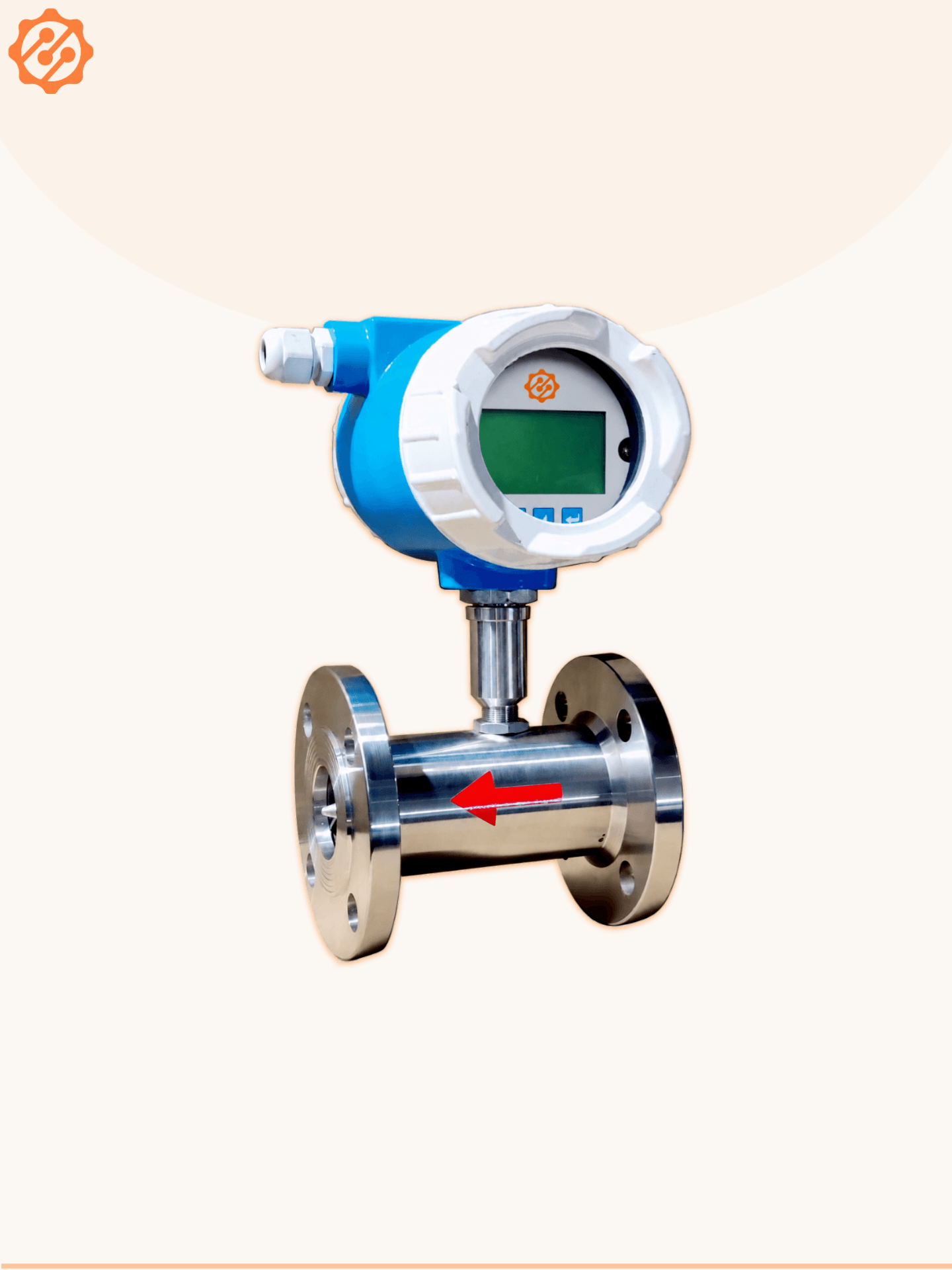
Turbine Flowmeter
Code: TFM-FL, Model: TFM-011
A turbine flow meter is constructed with rotor and blades that use the mechanical energy of the fluid to rotate the rotor in the flow stream. Blades on the rotor are angled to transform energy from the flow stream into rational energy. the rotor shaft spins on bearings. when he fluid moves faster, the rotor spins proportionally faster. shaft rotation can be sensed mechanically or by detecting the movement of rotor blades.
Rotor movement is often detected magnetically, where movement of the rotor generates a pulse. when the fluid moves faster, more pulses generated. Turbine flow meter sensors detecting the pulse are typically located external to the flowing stream to avoid material of construction constraints that would result if wetted sensors were used. the RPM of the turbine wheel is directly proportional to the mean flow velocity within the tube diameter and corresponds to the volume flow over a wide range.
Product Details
Technical Specifications
| Media | Liquids (Clear) |
| Viscosity | 100 cp max |
| Pick off Type | Magnetic sensor |
| Line Size | 15 NB to 150 NB |
| Display | 8 x 1 LCD / 4 x 1 LED, 8 x 1 LED |
| Type of Output | 4 to 20 mA DC, 2 wire / Pulse 30 mV |
| Calibration Range | As per requirement |
| Accuracy | +/- 1% F.S. |
| Linearity | +/- 1% |
| Repeatability | +/- 1% |
| Pressure Drop | Approx 0.28 kg/cm3 at max. flow |
| Turn down ratio | 10:1 to 100:1 |
| Process Temperature | 150 °C max |
| Process Pressure | 30 kg/cm3 max |
| Construction Material | Body, Bearing, Support & Flange - SS 316 |
| Rotor | SS 410 / SS 410 with Teflon coating |
| Shaft | Tungsten carbide |
| Power Supply | Loop powered, 24 V DC, External |
| Power Consumption | < 40 mW |
| Response Time | < 100 mSec |
| Temperature Coefficient | +/- 0.01% per °C |
| Transmitter Enclosure | Flame-proof, IP-65, IIA, IIB CMRI Certified |
| Process Connections | Flanged / Threaded / Tri-clover |
| Mounting | In-line (Horizontal OR Vertical) |
| Operating Conditions | Temperature 0 to 55 °C / Humidity 5 to 95% |
Line Size Selector Chart With Respect to Flow Range
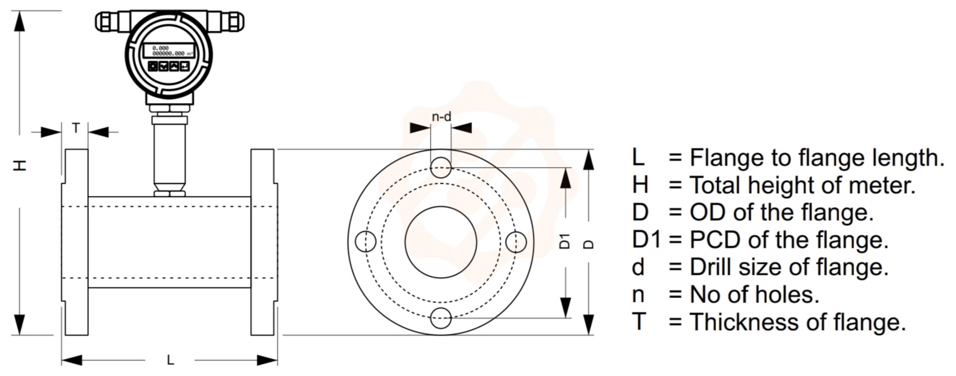
| Line Size | Flow Range M³/Hr | F/F Distance |
| 15 | 0.2-2.2 | 175/208 |
| 20 | 0.6-6 | 175/210 |
| 25 | 1-10 | 175/213 |
| 40 | 2.5-25 | 175/220 |
| 50 | 4.5-45 | 175/238 |
| 80 | 9-90 | 238/250 |
| 100 | 18-180 | 250/275 |
| 150 | 35-350 | 250/275 |
0
Verified Reviews for Turbine Flowmeter
Your Opinion Matters
We continuously evaluate and elevate our industrial engineering quality and delivery metrics based on client data.
View & Write Reviews